


Last time, I showed how to start putting together an AC arc welder from scavenged microwave parts, focusing on the transformer modifications. Now, I'll show you how to finish up your DIY stick welding machine by fixing up the electrical system and performing the finishing touches.
Before you watch this, make sure you've seen the first video.
WARNING: Stick welding, and/or the modification of a Microwave Oven Transformer (M.O.T), can be very dangerous and presents risks of UV radiation, shock hazards, burns, fires, fumes and a multitude of other risks. This project should not be attempted without a thorough understanding of electricity, adult supervision and adequate training. Misuse, or careless use, of tools or projects may result in serious injury and/or death. Use of this content is at your own risk.
I started this part of the project with a scrap piece of 3/4" birch I had left over from my "Router Table" project.
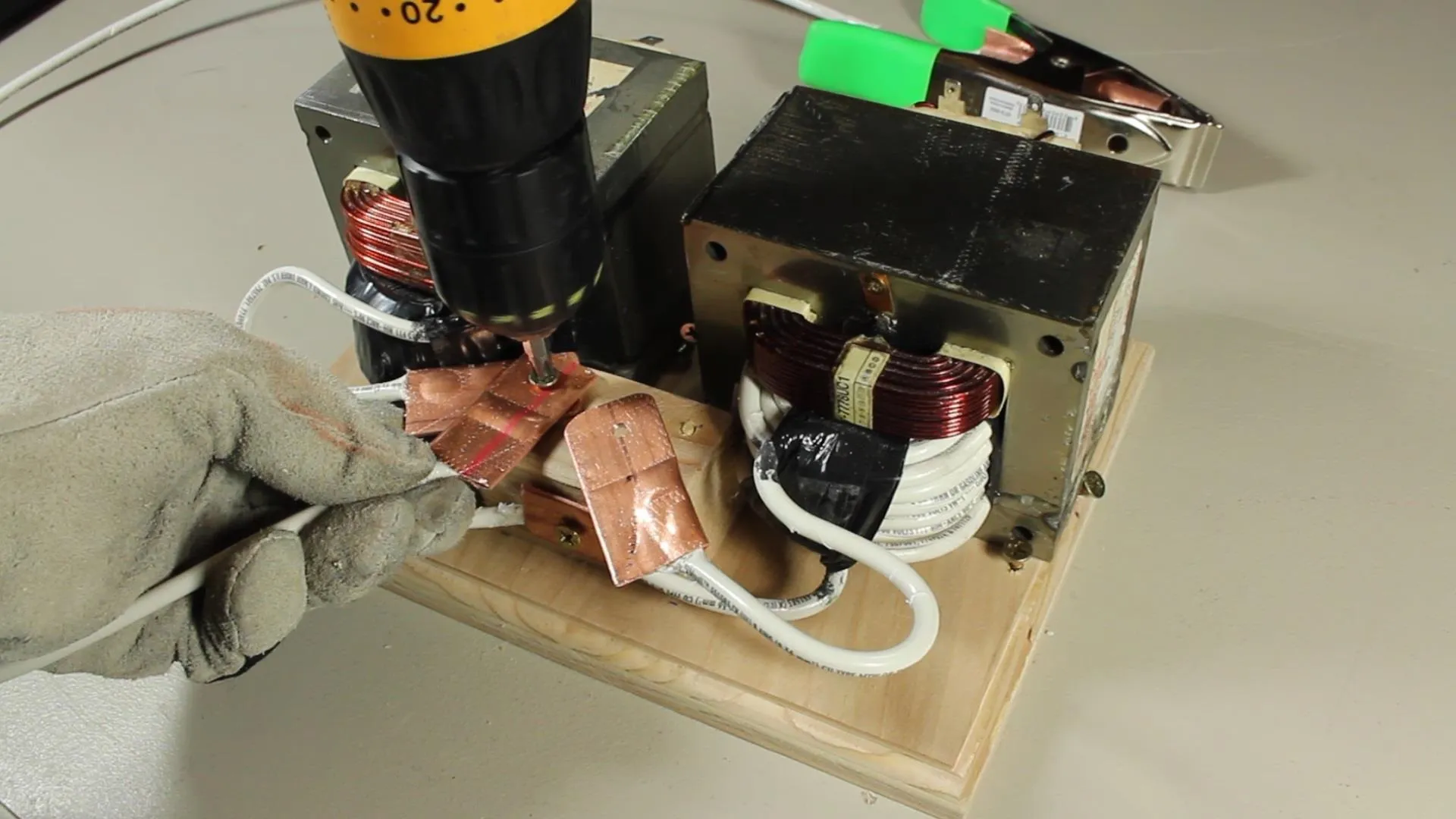
The measurements for the board were 7"x10", and that keeps this about as compact as practical. I found a piece of 2x2 as well, and screwed it onto the center of the board about an inch from the edge. Two pilot holes were drilled in the top to accommodate our electrode lugs.
I decided to use lugs here rather than keep it all one continuous cable, because it gives the option of changing out electrode cables, or easily modifying the electrical output for future projects.
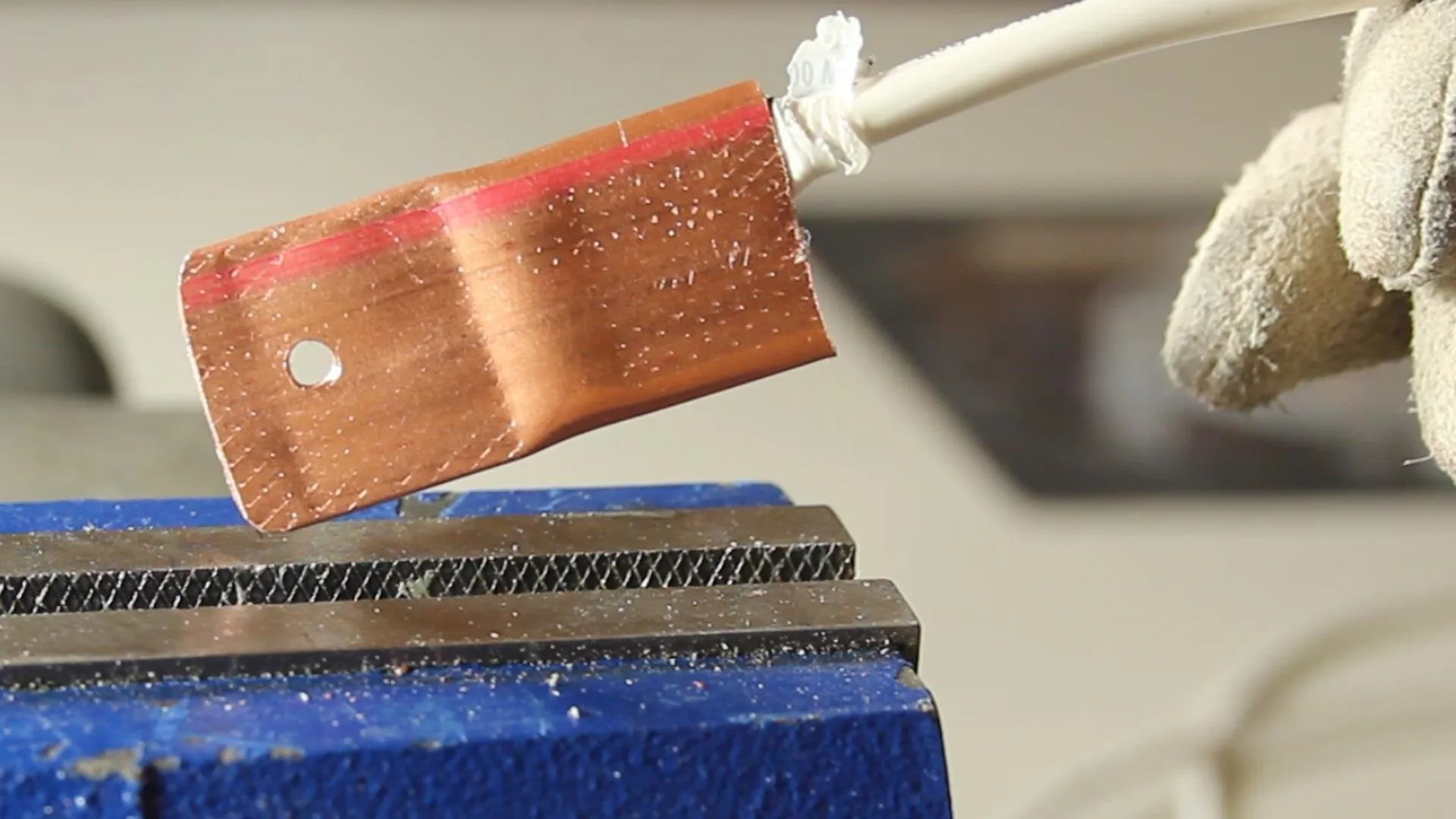
Copper lugs can be pricy, but I found that if I used a 2" length of 1/2" copper tubing, I could make my own.
I used a bench vise to crimp 1" of the tubing completely flat, then drilled a hole in the flat piece.
A belt sander helped to clean up the edges a bit to make it easier to handle, and make it look a bit nicer as well.
For the electrode cables, I used some of the 8awg cable left over from when we wound the transformer coils.
Next, I exposed the copper on the end of the cable, and bent it over so it would fit inside the lower part of the lug. I flattened it with a bench vise to make a solid electrical connection, and in my testing, the connection doesn't come apart.
If you don't have a bench vise, I imagine a hammer could work with very similar results.
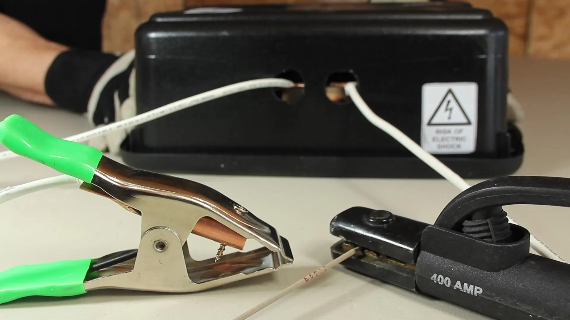
Since the system is AC, there really is no "ground" connection and it doesn't really matter which cable connects to which side, but I decided to put a "ground" clamp on the left side, and the electrode holder on the right.
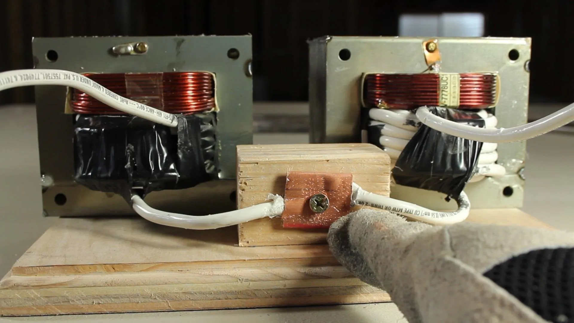

I also spliced the cable between the two transformers and connected them to a common lug so I could have the option to center tap the transformers for future projects, like powering an arc furnace for example.
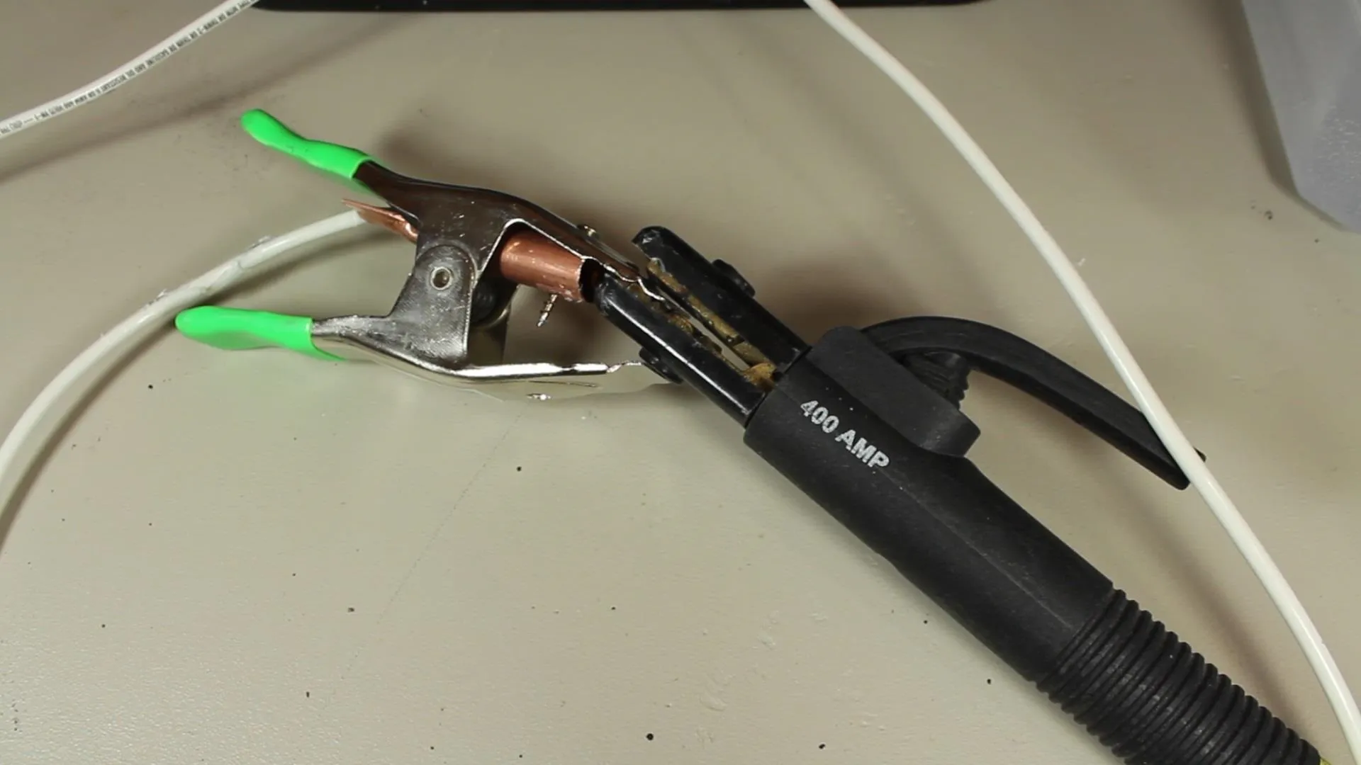
For the clamp, I found this metal one at the hardware store for only $0.99. When the rubber tips were removed, it could conduct electricity.
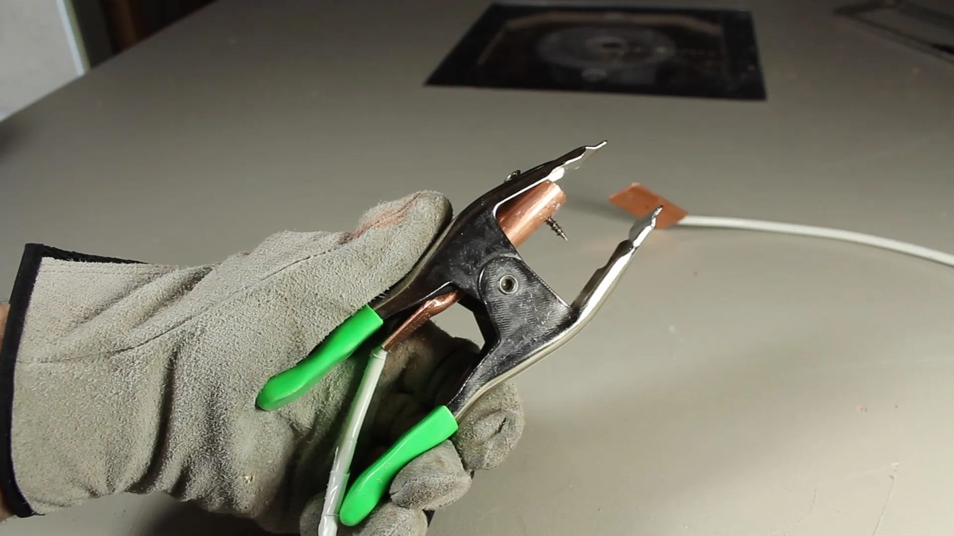
I crimped a piece of copper tubing to the wire, then secured the tube to the clamp with a screw. For being so cheap, the clamp had a surprising amount of clamping force, which was great for biting onto the workpiece.
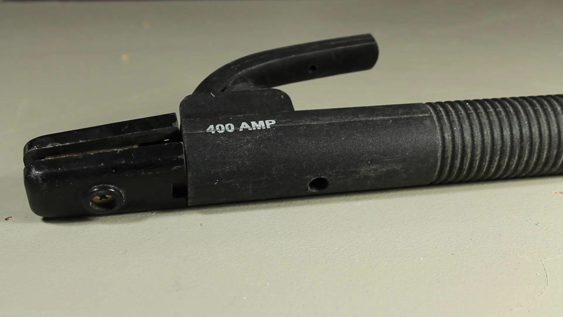
I bought a replacement electrode holder for $13 rather than making my own. It looked better and was much more practical for welding with.
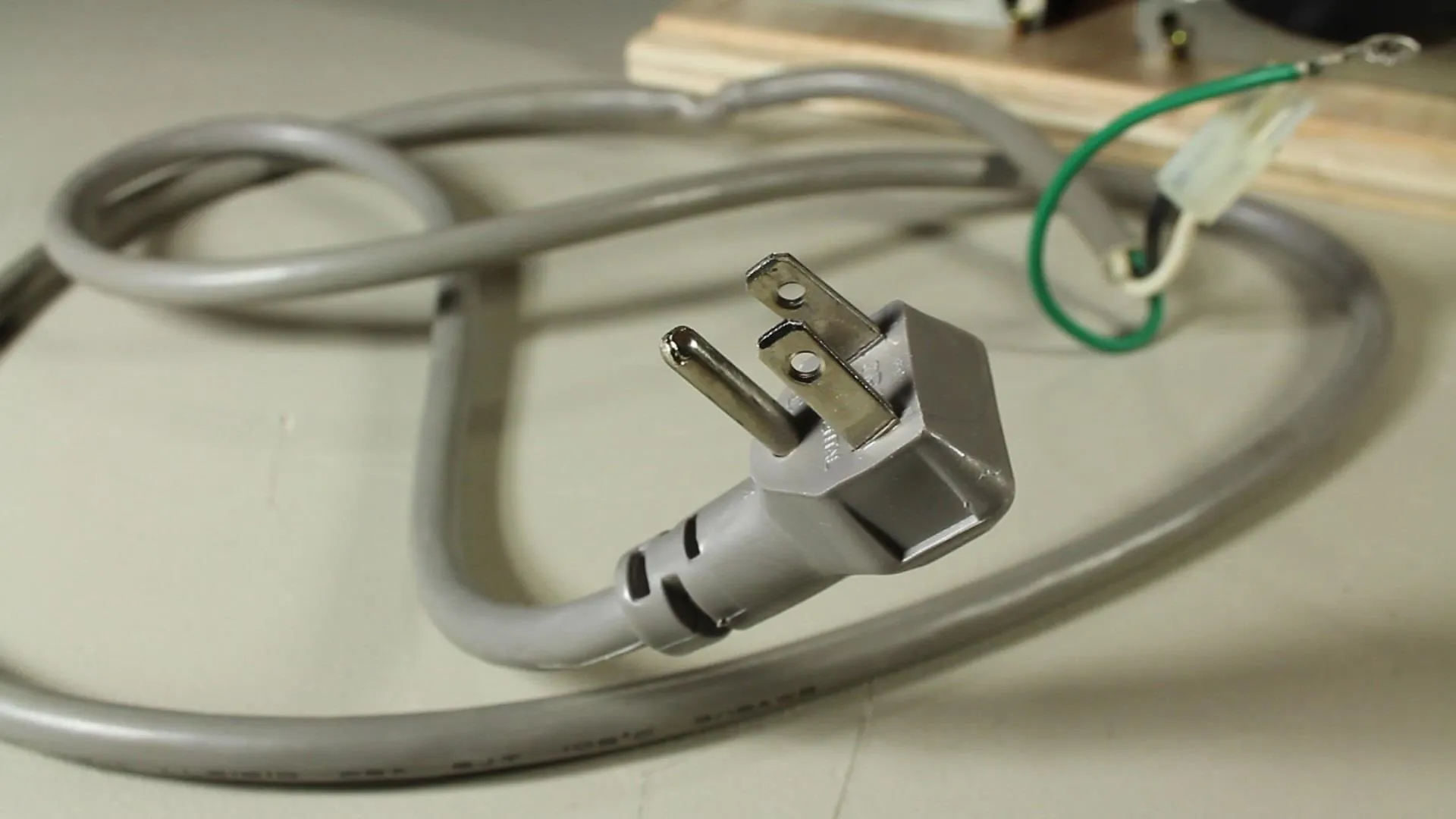
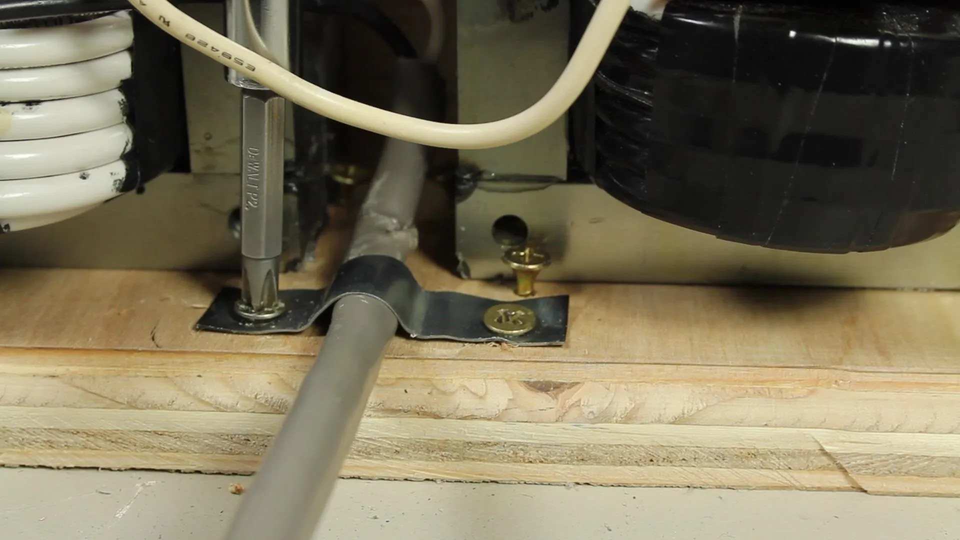
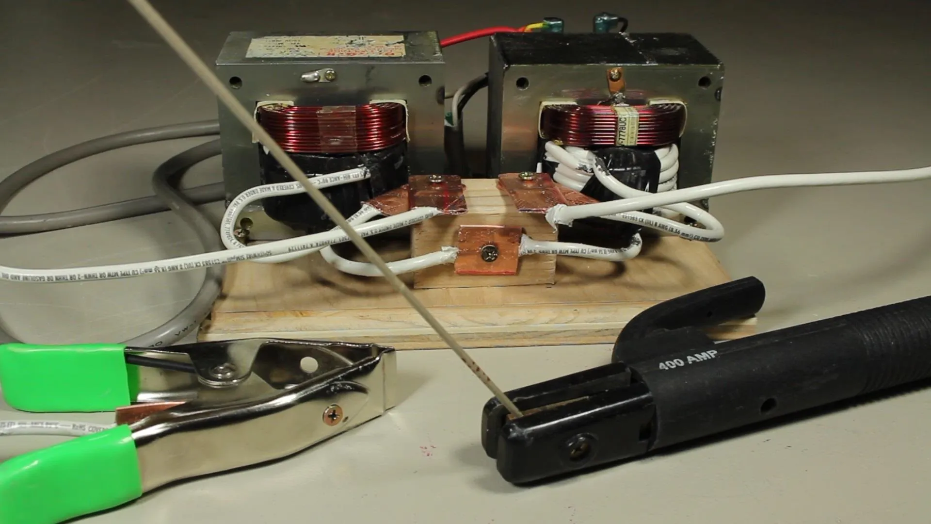
I used one of the cords saved from one of the microwaves and cut off the green wire, and secured the cable to the wood base to prevent the cables from pulling off the connections.
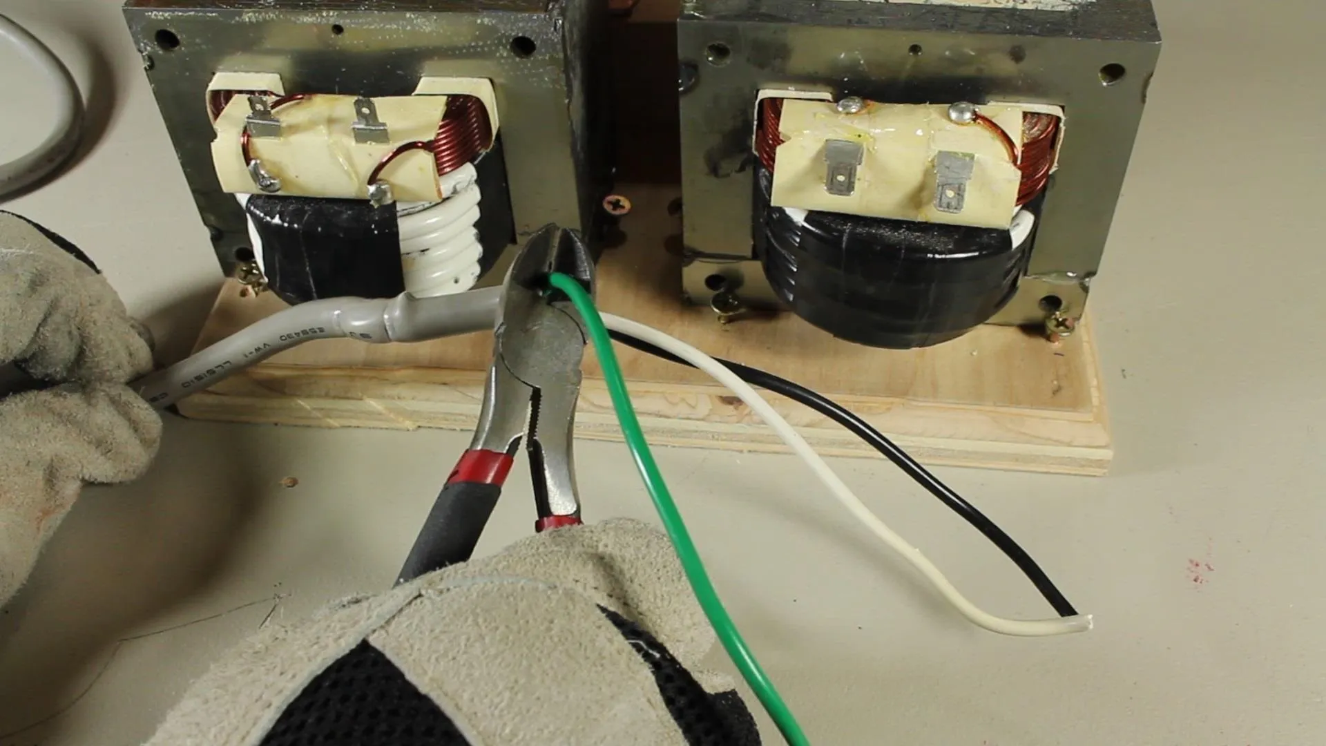
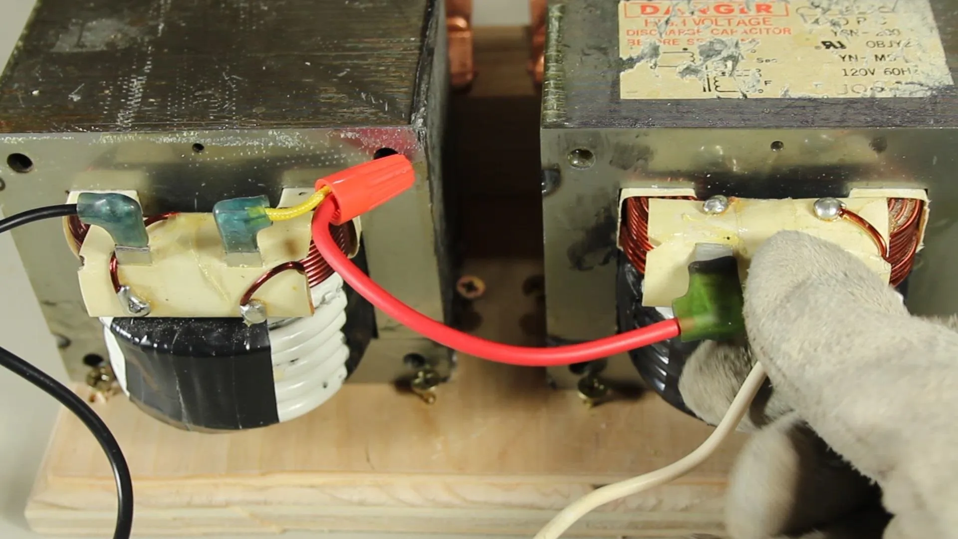
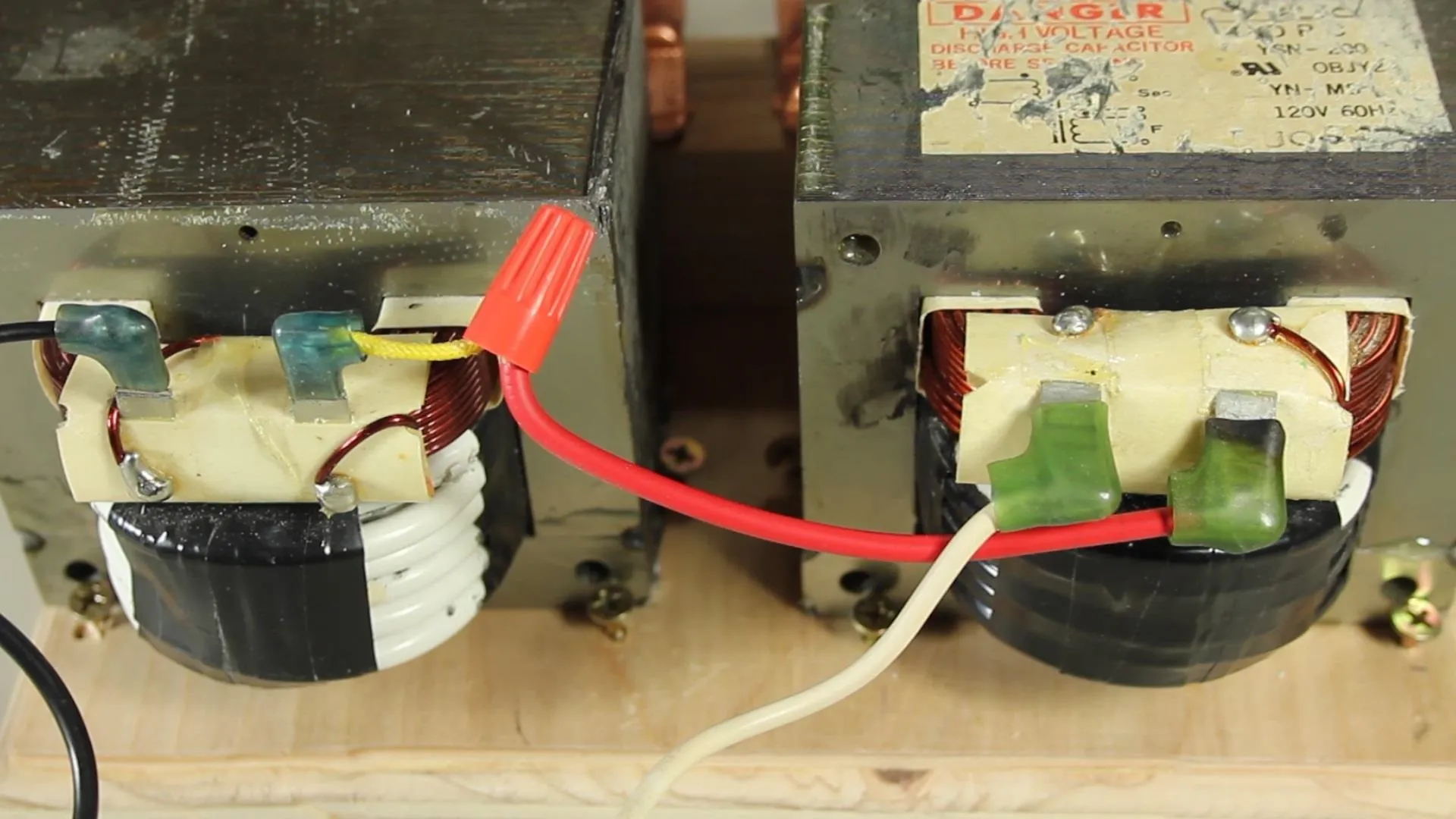
The black cable connects to one of the primary terminals on one of the transformers, and the white wire connects to one of the other transformers primaries. It doesn't really matter which one.
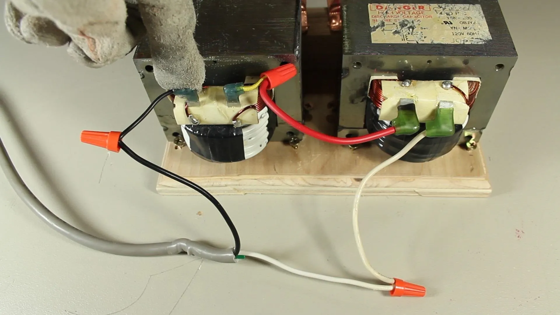
I used another piece of wire to connect the other 2 posts together, essentially connecting the 2 transformers in series.
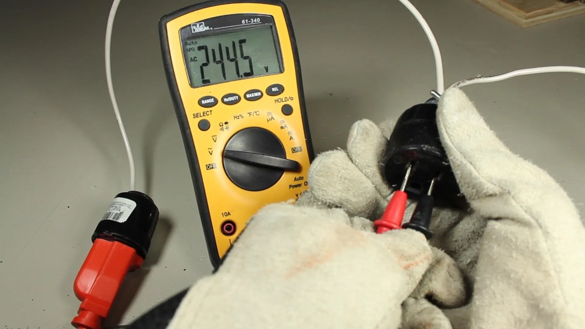
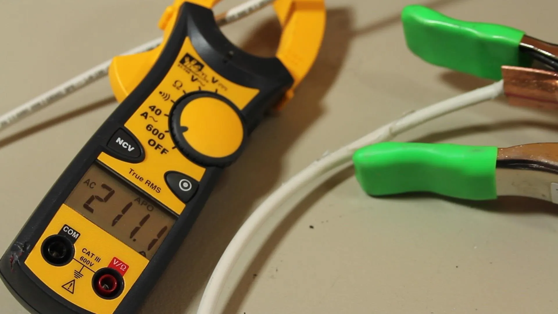
Later on, when the device is tested, the two electrodes should be outputting around 36 volts. If you're seeing very low voltage, like 2.4 in my case, that means the transformers are canceling each other out, and this can be fixed by just switching the connections on one of the transformers.
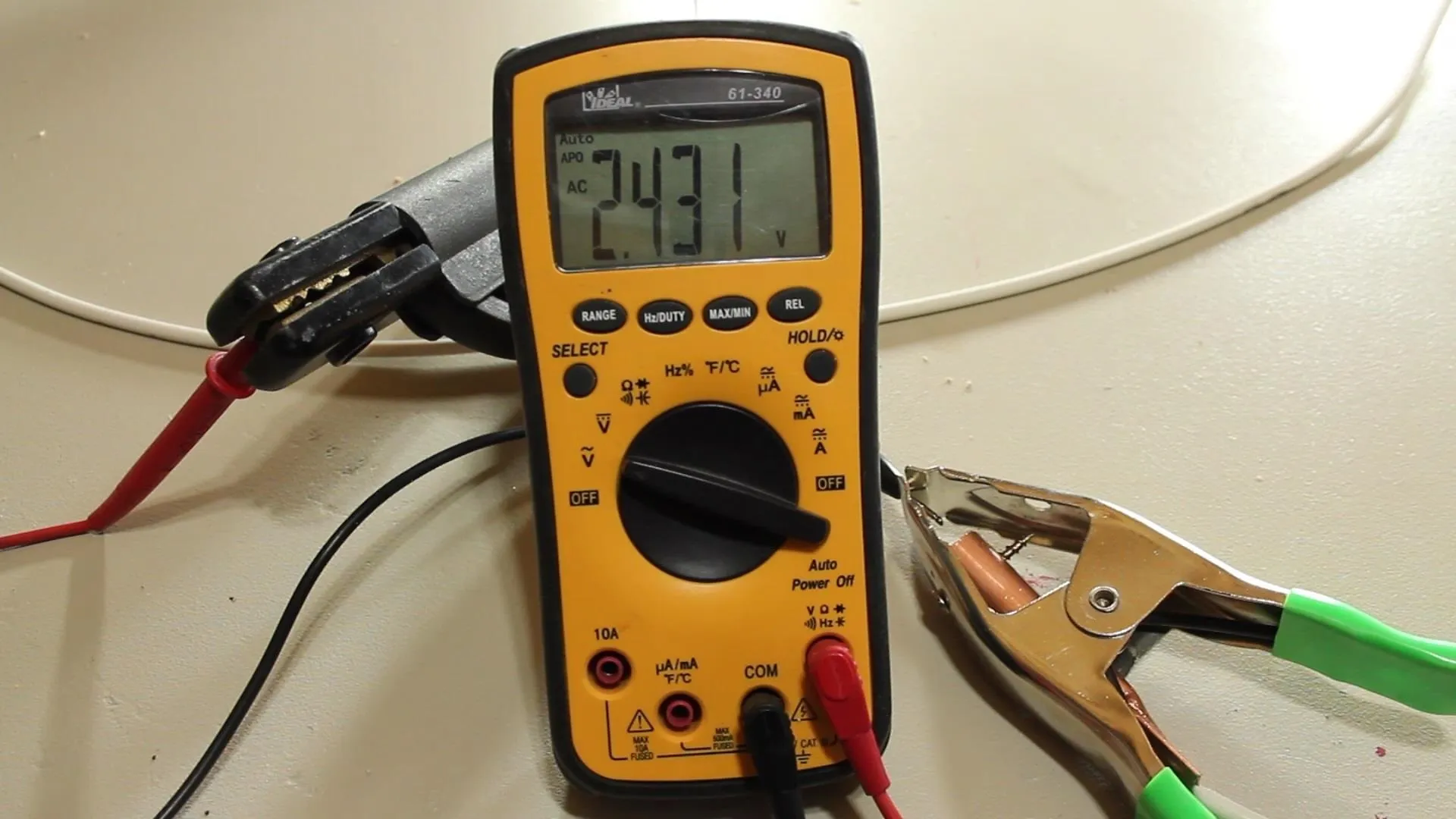
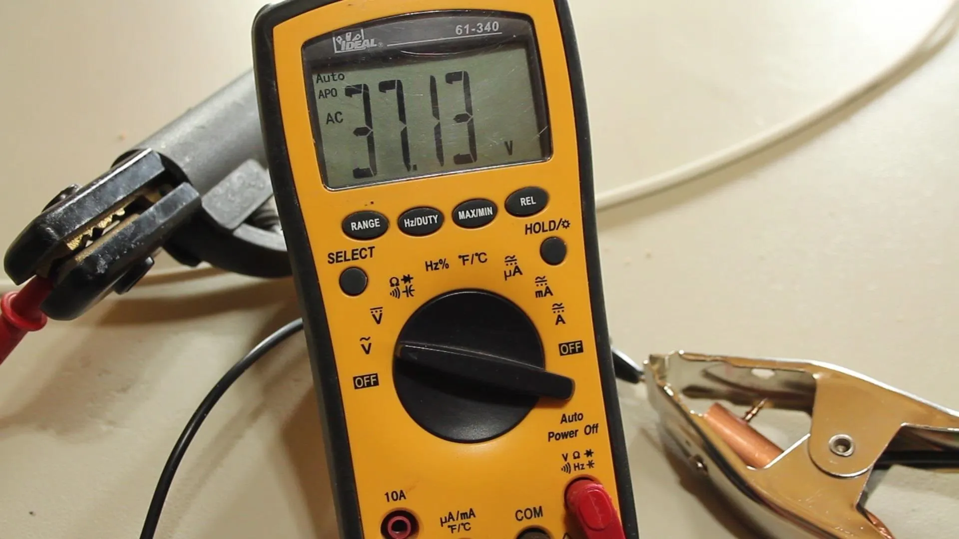
I went ahead and did that and ended up with about 37 volts between my ground clip and electrode holder.
I needed 240 volts AC to power this system, so I used 2 plugs, a connector, and some 10awg wire.

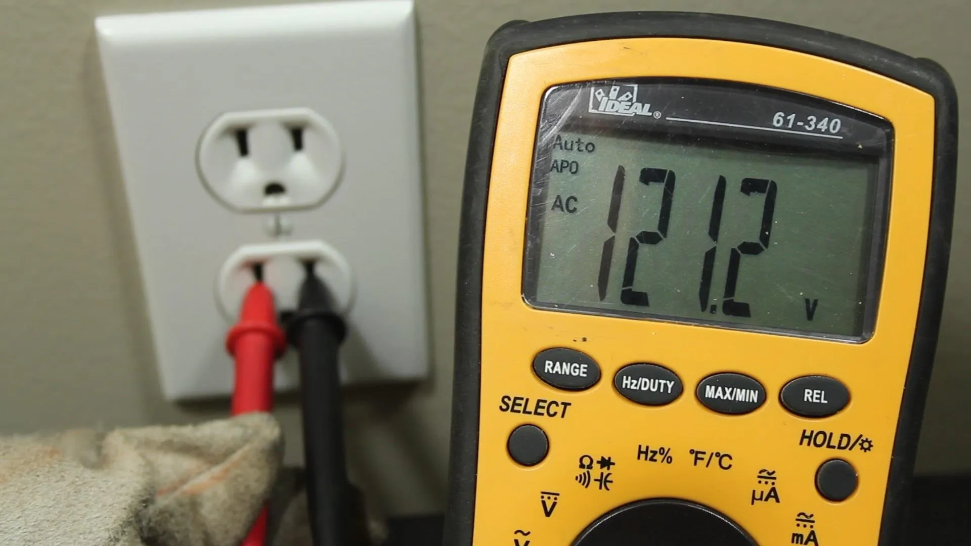
Each of the outlets in my house output around 120 VAC, and the circuits all connect back to the breaker bus bars. There are 2 busses, and I learned that if I took a hot line from each bus, the electrical potential between them was 240 VAC.
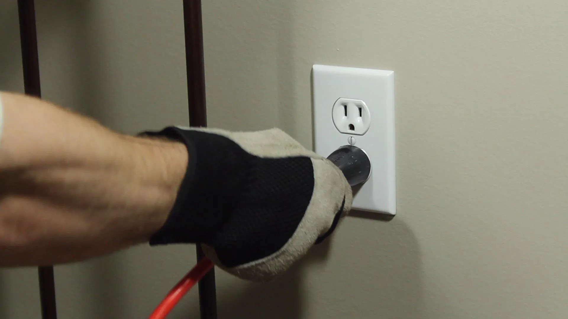
Rather than tapping into the breaker box directly, I used extension cords and connected to 2 different outlets that were 180 out of phase (on separate bus bars).
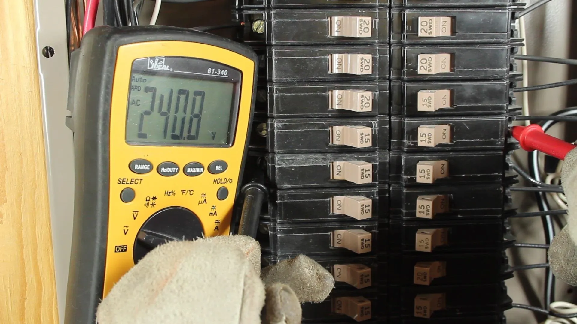
When they were connected to my adapter, the result was 240 VAC.
It's important to keep in mind that this welder doesn't have an on/off switch, and no current limiting of it's own. That's why I had to build a separate power controller I call the "Scariac". It's like a "Variac" except much more dangerous. But it is pretty cheap, and it gets the job done.
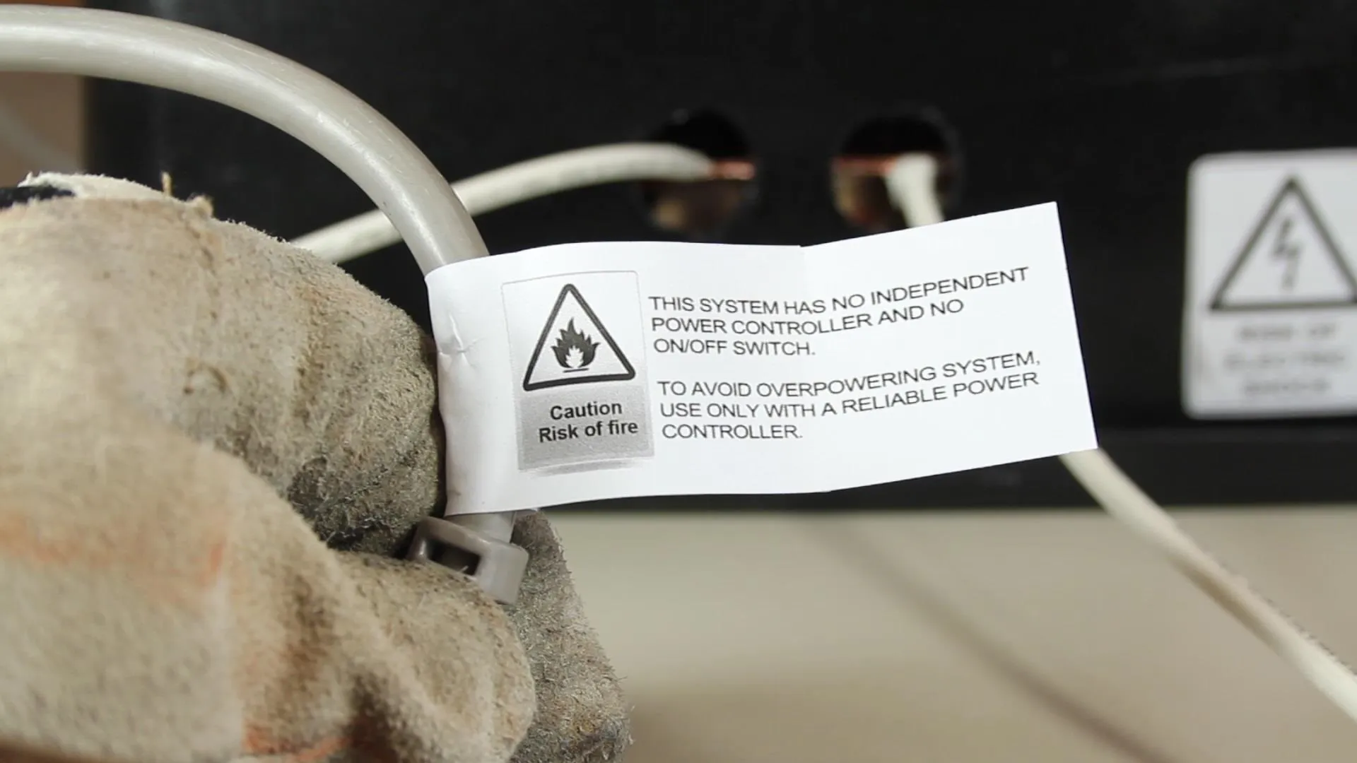
Look for how to build the Scariac in a different project.
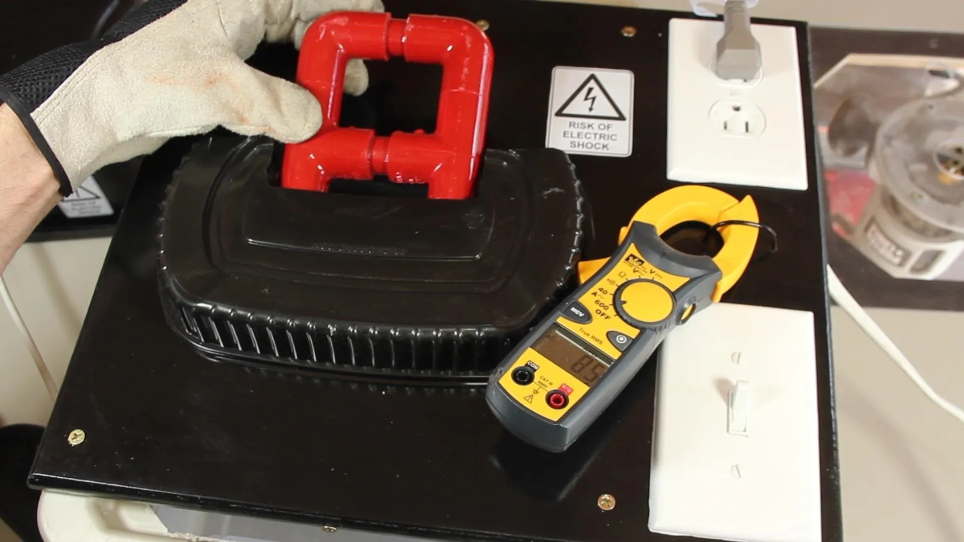
To set the current for welding 1/16th rods, I connected the ground clamp and electrode holder together, effectively shorting out the system. The Scariac has a loop of wire built in that allows me to monitor the primary current, and when it's set to about 15.5 amps on the primary, it gives me around 100 amps on the secondary.
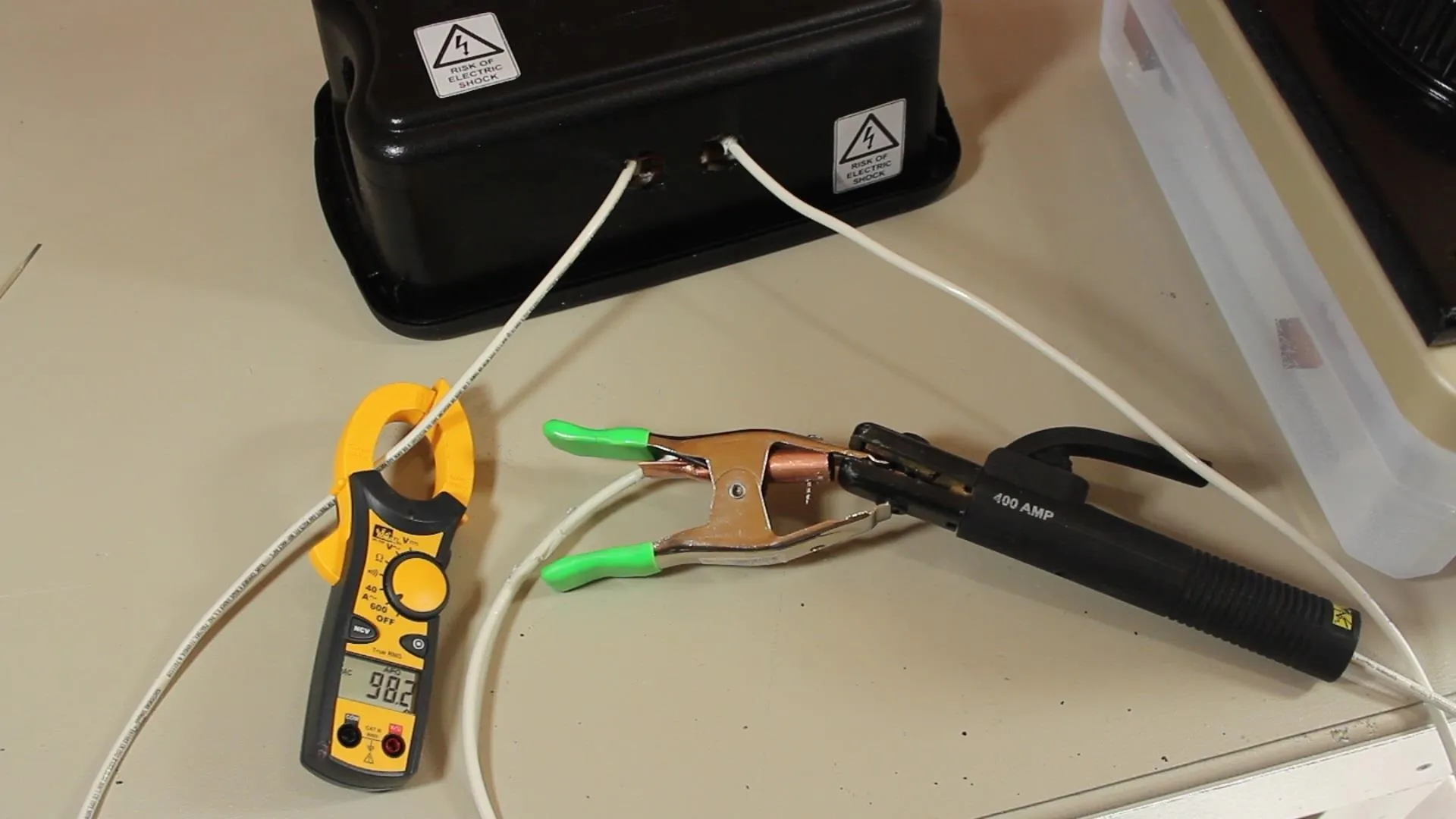
Cranking up the power on the Scariac can get the welding cables up over 200 amps, but I really don't recommend running them that high for more than a few seconds or the plastic coating on the cables will overheat and may start melting.
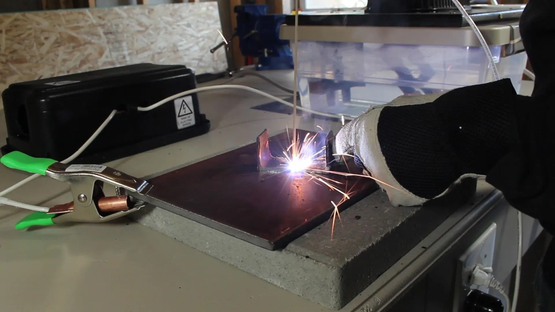
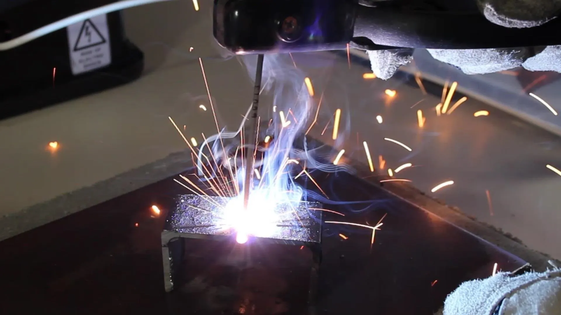
In any case, you can see there is certainly enough power for welding.
I burned ten 1/16 rods in a row, and the system was only warm to the touch. This gives me the impression it's got a pretty good duty cycle for use with the smaller rods, and these are probably the only one's I'll really need for my hobby use anyway.
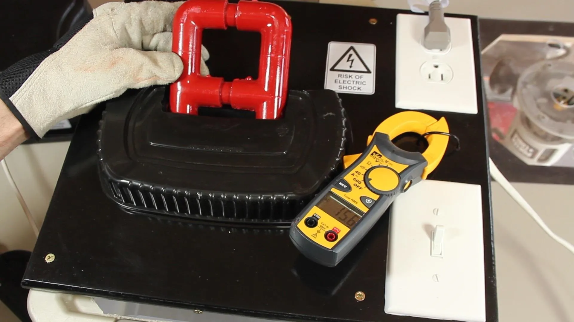
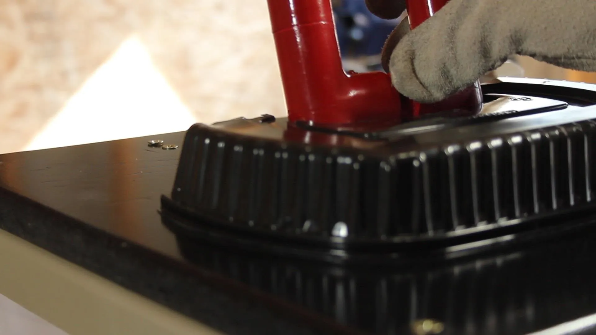
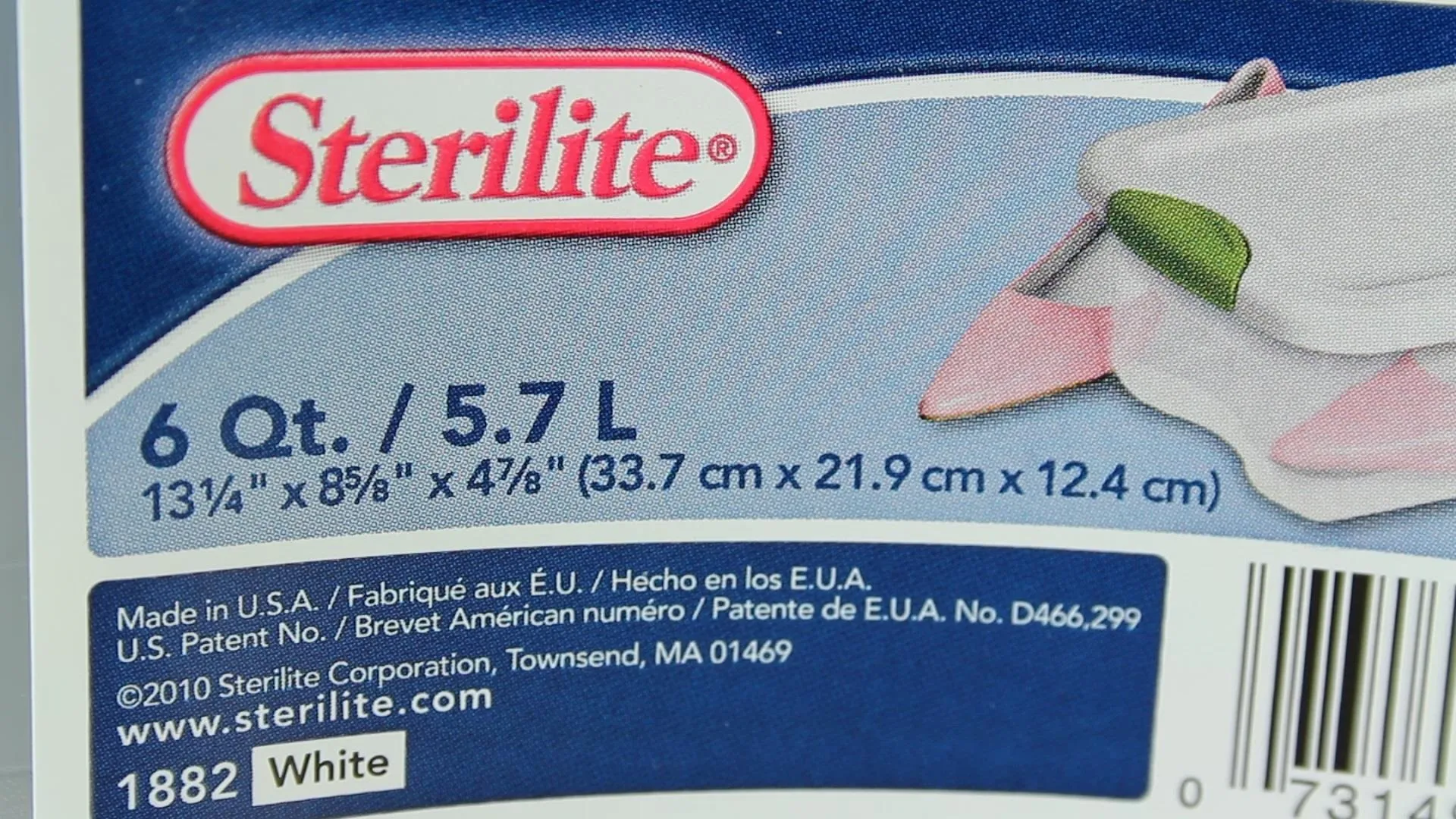
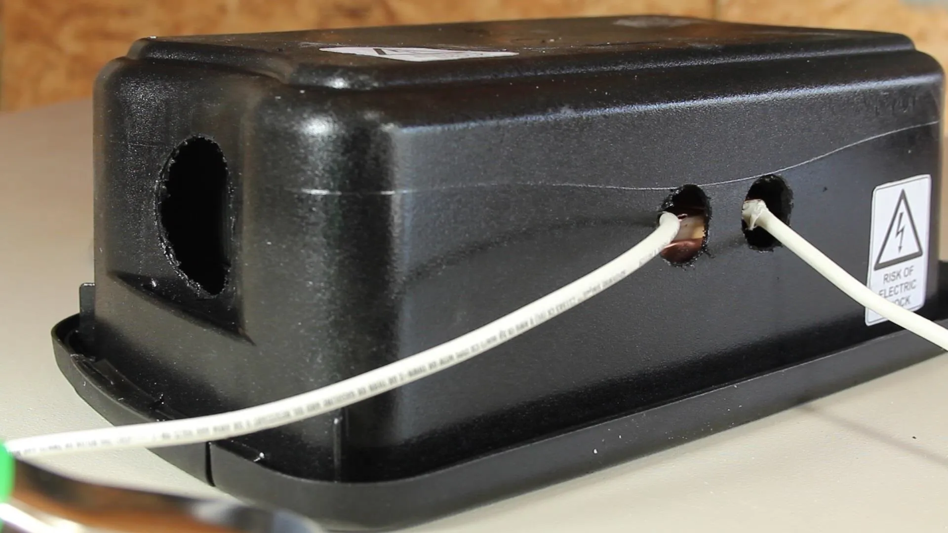
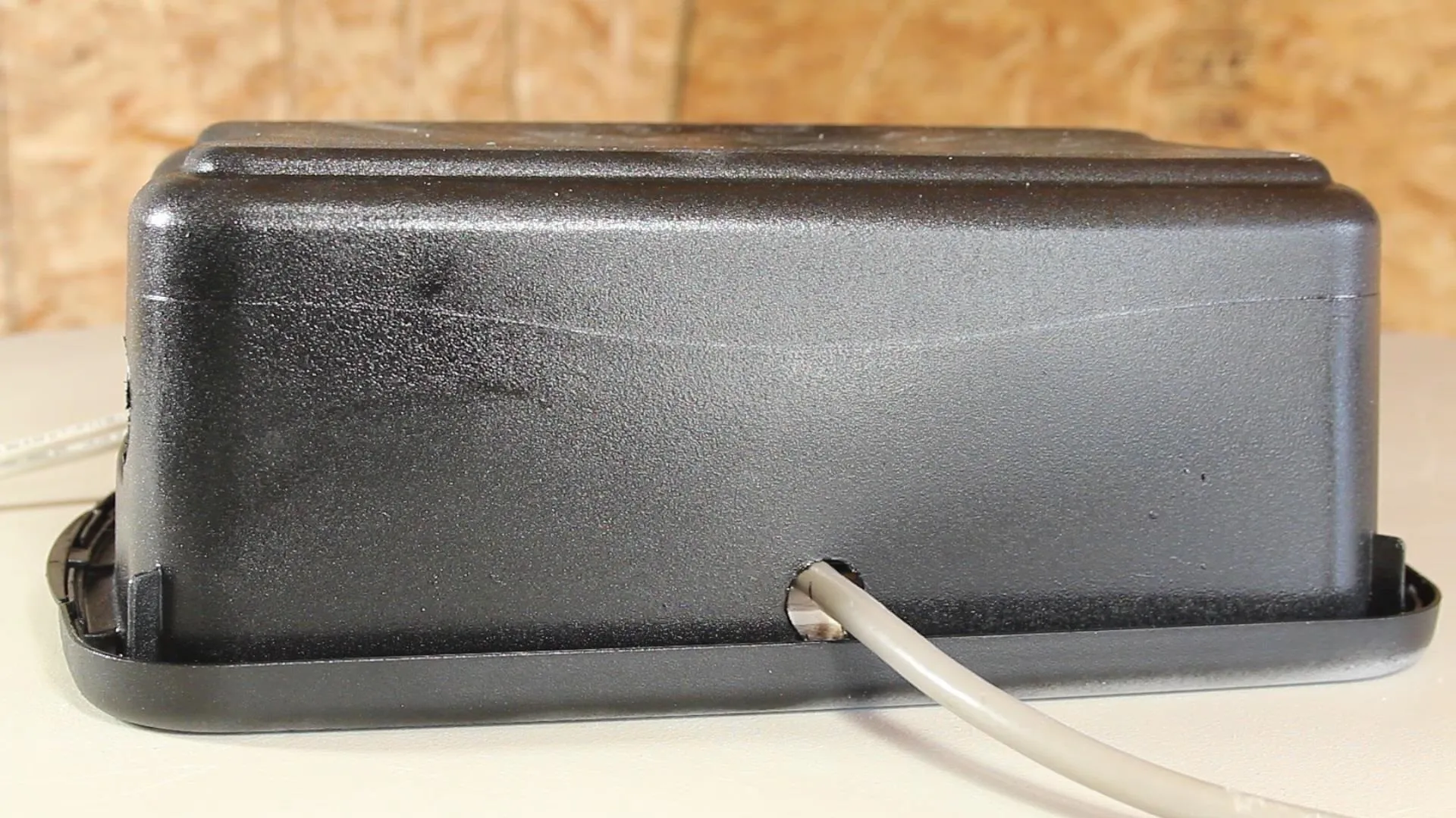
Rather than leaving all the terminals exposed, I picked up a plastic container, painted it black, and drilled a few holes for the cables.
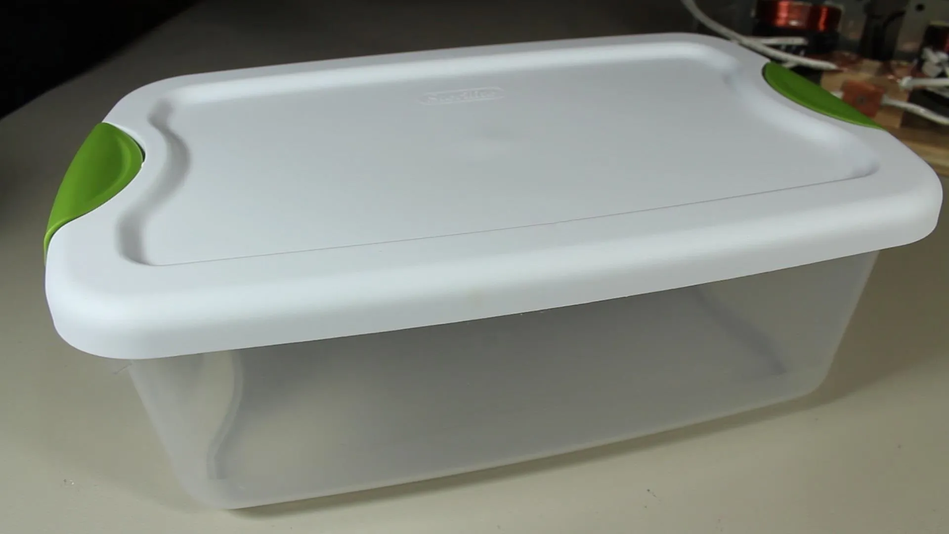
I used the top as the base, and the bottom as the top. It seemed to work pretty well.
There are also ventilation holes cut in the sides to allow airflow over the coils, and even consideration made for attaching a fan to blow cool air and help regulate the temperature while welding.
At this point, the system is completely finished and ready for welding!
You can see some of my first few experiences with the world of welding in the video below.
Well, there you have it! A homemade AC stick welder.
If you haven't see the video yet, it's not too late. Watch it here!
If you like this project perhaps you'll like some of my others. Check them out at thekingofrandom.com.


Comments
Be the first, drop a comment!